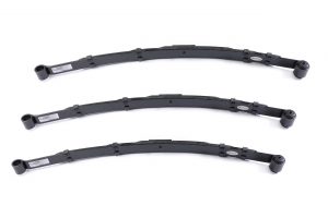
Leaf springs are the oldest form of suspension in racing. Although they are the oldest, they seem to be the least understood. Leaf springs possess many desirable suspension features, such as dampening, forward bite, roll over steer, high anti-squat percentage, and high lateral stiffness. In addition, the leaf spring suspension is more forgiving on chassis set-up errors. Due to the fact of the popularity of the leaf spring system, we felt racers may want to understand more about how the suspension actually works.
We will cover the different aspects of leaf springs from free rate to installed rate, applications, hook up points and other performance enhancing factors.
There are four basic types of leaf spring systems in the racing industry today.
HOW TO EXAMINE AND CHOOSE YOUR HIGH PERFORMANCE LEAF SPRING
Only use springs manufactured by companies such as LANDRUM SPRING that have a complete manufacturing facility. This insures properly made springs, guaranteed arch tolerances, access to complete labs for testing and research with technical racing experts to understand your requirements.
Examine the spring immediately upon receiving. Verify the leaf spring for consistency in the arch. A typical problem is a spring that has excessive arch in the center. When installing these springs, the arch will be pulled out, creating higher stress on the spring that will eventually decrease the life of the spring.
Multi-Leaf springs used for racing should have a clench clip type system. This system involves riveting the clips onto the leaves; the advantage is in preventing the clips from sliding up the leaf and becoming loose. The clip is installed by using a hydraulic press to assure proper tightness. An inconsistent clip, such as the Kwick Clip or Banding Clips with rubber insulation, will transfer into an inconsistent side bite. The disadvantages of banding clips with rubber linings is that the rubber will absorb grease and brake fluids leading to deterioration of the components. In addition, banding clips are frail and tend to break under impact or stress. These lightweight clips simply cannot withstand the tremendous forces encountered in racing leaf springs.
Multi-leaf springs used for racing should incorporate leaves that are “diamond trimmed” on each end, not leaves that are tapered on the ends. Tapered end leaves have a gradual decrease in thickness on each end. The tapering thicknesses are inconsistent which translates into inconsistent spring rates. Leaves that are tapered on the ends are generally used for “mass production” applications which do not require the close tolerances and consistency in the spring rate that racers demand. Squared end leaves produce high stress points in each leaf leading to premature failure of the leaf. Negative effects include limited number of spring cycles, loss of spring life, and loss in ride heights. Furthermore, the leaves should include Teflon inserts on each end to reduce inner leaf friction.
Ask your supplier what materials the spring consists of. LANDRUM SPRING has the proper mixture of chrome vanadium, carbon, manganese, silicon, nickel, molybdenum and tungsten. This not only insures consistent and proper spring rate, but also longer life (more cycles).
WHAT’S EXPECTED OF A LEAF SPRING
Leaf springs perform the following tasks:
Due to all the loads leaf springs are under, it is one of the most stressed components on the race car.
WAYS TO ENHANCE PERFORMANCE AND LONGEVITY OF LEAF SPRINGS
Running dampening shocks not only will tighten the car on entry, but will also prolong the life of the spring. The leaf spring will last longer because the shock will assist in absorbing the dampening forces.
Driving style plays a major role in the life of a leaf spring. Slinging the car into the corner or spinning out puts an extreme amount of lateral force on the springs which in turn, causes premature failure.
Impact from tire hopping or grazing the wall can bend or unroll the main leaf eyes. This can cause an undesirable change in spring rate and wheel base settings.
Choosing too light of a spring rate will cause the spring to be in a higher stress situation, thus losing ride height. Furthermore, the spring will absorb all the weight transfer, and not plant the tire securely on the track. Too light of a spring rate will also cause the rear end to lose an excessive amount of pinion angle under acceleration, leading to a loss of forward bite.
When not racing, keep the springs unloaded by simply placing a jack stand under the chassis frame rail. This simple task will increase the life of the leaf spring dramatically.
If the leaf spring’s hook-up points are installed on the chassis incorrectly the misalignment will produce high stress loads on the spring. In turn, the life of the spring and the number of cycles is reduced.
Bushing choice will also affect spring life, and more importantly, spring performance. Rubber bushings tend to absorb more energy and loads from the chassis and rear end, therefore the springs tend to last longer. However, under racing situations, this may cause the chassis and rear end to have excessive movement, thus producing erratic handling.
Pivot bushings are bushings that were designed to remove the bind between the chassis and the spring. However, the negative effects of these bushings greatly outweigh their intended purpose. Our extensive testing has proven this component to produce very erratic handling characteristics. When the front bushing is allowing the front leaf spring to pivot, it transfers all the side loads and lateral forces to rear portion of the leaf spring and shackles or sliders, which were not designed to handle the additional stress. This leads to bent shackles, warped sliders and misaligned axis points. Furthermore, because the front eye is allowed to pivot, it does not have any solid displacement to drive the car forward.
Problems with front pivot bushings are:
Urethane and aluminum bushings tend to transfer more energy and loads directly to the spring. This prevents undesirable chassis and rear end movement, thus creating favorable synergy between the chassis, springs and rear end. These bushings produce a solid rear housing displacement for added traction. Furthermore, these solid bushings control and enhance chassis performance by resisting chassis roll/torque. Solid bushings provide stable and predictable handling characteristics that lead to more consistent lap times.
LEAF SPRING RATE
The rate of a spring is the change of load per unit of deflection (N/mm). This is not the same amount at all positions of the spring, and is different for the spring as installed. Static deflection of a spring equals the static load divided by the rate at static load; it determines the stiffness of the suspension and the ride frequency of the vehicle. In most cases the static deflection differs from the actual deflection of the spring between zero and static load, due to influences of spring camber and shackle effect.
Free rate is the rate of the spring when it is out of the chassis. The spring’s length, width, thickness, number of leaves, hardness, bushings and clips determine the spring rate. The free rate is generally progressive, meaning that the leaf spring rate does not increase proportional to the rate of deflection.
Generally the spring rate will increase when the following is done or decrease on the opposite. The length decreases, the width increases, the thickness increases, the number of leaves increases, Brinell hardness increases, utilizing a harder durometer bushing.
Bushing choice can affect spring rates. Rubber bushings tend to promote softer rates than solid bushings.
Clips have a profound effect on spring rates.
Figure 1 Band Clip |
Springs with banding type clips (see Figure 1) with rubber insulation produce inconsistent spring rates due to the fact of various durometer hardnesses and the deterioration of rubber compounds. The rubber, many times, will fall out due to the rigor of racing. Also, common mishaps of spilling brake fluid or brake fluid contact from simply bleeding the brakes will deteriorate the rubber and break the composite down; therefore, the rubber will fall out and the clips will be loose and slide down the main leaf. Furthermore, band clips are frail and tend to break, stretch and fail under minimal contact (opponents right front fender hits your left rear spring).
Clench clips (see Figure 2) have been proven to maintain a more consistent spring rate because of its ability to retain its clamping force.
Figure 2 Clinch Clip |
The leading edge of each leaf plays a role in determining spring rates. Through our research, diamond trimmed leaves produce the most consistent spring rate. Tapered leaves have inconsistent run out, thus inconsistent spring rates.
Installed rate is another rate all together. The installed rate is the rating of the spring as it is positioned within the chassis itself. Leaf spring rates can be increased or decreased based on the mounting positions and angles. For example, when the leaf springs are toed in (the front eye locations closer together than the rear mounts) the lateral rate or twisting resistance is increased, therefore one’s side bite rate is increased.
The inboard mounting position of the springs play an important role as well. The closer the leaf springs are mounted together (inboard), the more pressure the chassis exerts on the springs through physical leverage. As a result, the inboard springs are mounted the softer the installed rate will be. The opposite occurs when the springs are mounted outward (closer to the wheels).
Installing the leaf spring directly to a fixed axle seat (no upper or lower rubber mounted pads which are common on GM’s) will increase the overall spring rate, wrap-up rate and lateral rate, as well as the braking rate.
Shackle angle determines the rate as well. A shackle with a 3 degree layback incorporates a stiffer installed rate than a shackle at 25 degrees layback. In addition, as the spring is put under load the shackle angle increases; therefore, the spring rate decreases under travel. To determine the effective angle of a shackle, pull a string from the center of the front eye to the center of the rear eye of the spring, and then a line from the rear eye through the shackle pivot point. Measure the angle derived from the two lines. You can decrease the spring rate by increasing the angle, or increase the rate by decreasing the angle. Also, excessive torque of the shackle bolts will increase the installed rate.
LANDRUM SPRING and many of the top chassis manufacturers recommend that the shackles never extend straight back. This will produce a lock-up or binding effect and the car will perform erratically and unpredictably.
Shackle rigidity and length play a role in the installed rate as well. If the shackles are long and do not have any middle support or bracing, then the shackle tends to absorb more of the twisting instead of the spring; therefore, your lateral resistance is less. Also, the longer the shackle length, the slower the arc movement which decreases the rate of the spring change. The opposite holds true, the shorter the shackle, the faster the rate of change.
A common misconception is that arch affects free spring rate, which it does not. However, it does affect the installed rate. For example, if the main leaves are the same length and one spring has more arch, the spring with the most arch will have a stiffer installed rate. The reason – less shackle angle, more preload on each leaf, and a taller resistance line. Listed below are the effects of spring arch.
Less Arch | More Arch |
---|---|
|
|
LANDRUM SPRING’S engineers have found that by using two of the same spring rates, but installing one of the springs with a higher arch (for example on the left rear) is not recommended. What happens is that the car responds as if it has a stiffer spring on the left rear; however, because it has more arch, the spring is under a higher stress load. Therefore, decreasing its long term effectiveness and life. When using coil springs on the rear, changes are made with spring rates not the free height of the coil springs. For example, if you want 250 lbs. on the left rear and 225 lbs. on the right rear, you should not install a taller spring on the left rear with the same spring rate as the right rear. One should use the same free height, but change rates. The same theory applies to leaf springs. To increase resistance on the left rear, one may incorporate a 225 lb. and a 200 lb. right rear leaf spring with matching arches. The wedge/bite will be determined by the rear spring split (different spring rate from left to right) combined with the front springs and the size of lowering blocks used. Furthermore, the life of the spring will be extended due to the fact it is not under high stress, but more importantly, handling will be consistent.
When should one use high or low arched springs? Higher arch springs tend to work better on the dirt tracks whereas the lower arch springs perform better on the asphalt tracks.
Also, by increasing the lowering block height, one will be raising the axle height or lowering the front eye which will increase chassis roll. This tends to tighten the car on corner entry and through the middle of the corner. When using lowering blocks, remain in the 1″ to 3″ range. Anything over 3″ tends to be excessive and decreases forward bite due to the fact that the torque wrap up or forward thrust resistance of the rear end increases, therefore not allowing any wrap up or torque dampening to occur.
On parabolic and multi-leaf applications, it is not recommended to run a torque device, such as a torque arm or a spring or rubber torque link. The front half of the leaf spring should be sufficient to control rapid positive torque. Installing a torque device combined with these types of suspensions will cause the wrap-up rate to be excessive. The effect will be a lack of forward and side bite under acceleration. A dampening shock may be used to tighten the car on entry. This can enhance the life of the leaf spring because the shock will be absorbing some of the braking forces.
When towing the race car, avoid strapping the vehicle by the chassis. This puts undue stress on the leaf springs.
Proper U-bolt selection is critical, use only Grade 5 U-Bolts. Softer grades tend to stretch under stress created while tightening instead of maintaining compression between the spring and axle perch. Maximum U-bolt torque for 1/2″ diameter, plated U-bolts are 45 lbs. Always use Grade 5 washers and deep well nuts.
Never over torque the stationary end (front eye) bolts, as it will prevent the suspension from moving freely. Recommended torque is 20 lbs. Because the torque requirements are low, it is suggested to always use self-locking nuts to prevent nuts from backing off. This applies equally to the shackle and slider ends.
With the exception of U-Bolts LANDRUM recommends Permatex Anti-Seize on all leaf spring bolts, pivoting points, and slider components to promote free movement in the suspension.
MEASURING ARCH OF A LEAF SPRING
The true arch of a leaf spring is derived from the measurement between the main leaf the leaf containing the bushings, and the “datum line” (the line that intersects the center of the front and rear bushings). Measuring the arch from the floor up to the main leaf is referred to as “table arch.” LANDRUM SPRING does not recommend using this method to accurately measure spring arch. Different bushing diameters and unleveled floors will lead to inaccurate measurements. (See Figure below.)
TRUE ARCH | TABLE ARCH |
---|---|
Leaf spring mounting angles are one of the most important factors in a leaf spring system. In fact, it is more important to get the mounting angles correct than selecting the proper spring rate.
No matter what spring you put on the car it may not perform properly if the angles are misaligned.
To counteract the effect of incorrect mounting angles, you may have to install erratic spring rates, shock rates, wheel off sets, unsuitable ride heights, and/or undesirable tire stagger, each of which will cause unpredictable handling characteristics.
The following information and diagram may be beneficial for installing and checking mounting points.
The following information applicable for most oval track Chrysler styles mono and multi-leaf leaf spring applications with the sliders mounted on the rear.
The information below is applicable for most oval track Chevrolet styles, parabolic and multi-leaf leaf spring applications.
The following diagram illustrates a top view of the rear leaf springs which may be useful in determining a splayed or toed in pattern of the oval track Chrysler set up.
LANDRUM | AFCO | HOWE |
---|---|---|
20-236ML | N/O | N/O |
20-238ML | N/O | N/O |
20-240ML | 20241 | L50M |
20-241ML | 20241 | L51M |
20-242ML | 20242 | L20M |
20-243ML | 20242-1 | L21M |
20-244ML | 20242LW | N/O |
20-250ML | N/O | N/O |
20-220SPD | 20231L | L21 |
20-220SPA | 20230L | L20 |
20-230SPD | 20231 | L31 |
20-230SPA | 20230 | L30 |
20-231SPD | 20231HD | L31 |
20-235SPA | N/O | L30 |
20-235SPD | N/O | L41 |
20-235SPA | N/O | L40 |
20-240SPD | 20231XHD | L51 |
20-240SPA | N/O | L50 |
20-248SPD | N/O | N/O |
20-248SPA | N/O | N/O |
21-338SPD | 20228LW | L21C |
21-338SPA | N/O | L20C |
21-340SPD | 20228 | L31C |
21-340SPA | N/O | L30C |
21-342SPD | N/O | L41C |
21-342SPA | N/O | L40C |
21-344SPD | 20228HD | L51C |
21-344SPA | N/O | L50C |
21-348SPD | N/O | N/O |
21-348SPA | N/O | N/O |
21-140SP | N/O | N/O |
21-142SP | N/O | N/O |
21-144SP | N/O | N/O |
21-146SP | N/O | N/O |
42-450SP | 20311 | N/O |
42-452SP | 20311L | N/O |
42-454SP | 20311HD | N/O |
Click here to download as PDF.
LANDRUM SPRING is not responsible for any incorrect information listed
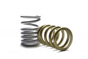
Coil springs are the most common used spring in most all motor-sports today. The reason is because it is very easy to change the component as well as check the rate, unlike leaf springs and some total hydraulic shock suspensions. Furthermore, with the incorporation of the coil-over spring/shock type suspension, the coil spring and shock ratio is close together and operates as one unit. Of the many components that can be changed on a race car chassis, the coil spring change brings about one of the most adverse effects on a chassis.
When choosing a brand of coil springs several issues should be addressed.
MATERIAL The use of a high quality material such as chrome silicon steel is used to assure a long lasting spring that will maintain a consistent rate and hold free height over many cycles. In addition, the choice of this material will allow a manufacture to wind the spring out of smaller wire to incorporate a larger pitch, which will inadvertently allow more travel and produce a lighter weight spring. In some instances the manufacture may have to choose chrome vanadium wire, instead of chrome silicon. Some springs may need .780 or .810 wire so as to not to be high stressed. Chrome silicon generally comes only in no larger than a .625 size from wire suppliers in the USA. If a manufacturer decides to produce a spring utilizing chrome silicon (.625) wire in lieu of a .710 where the stress levels are too high, then the spring will more than likely loose free height, take set and even in some cases break. So in some cases, using chrome vanadium for higher rated springs is a better choose than chrome silicon.
DESIGN: Most coil spring failure is directly related to the design of the spring. It is important to design the spring to its environment as well as its intended use. Pitch is the distance between the wires on any given coil-spring. Coil springs wound with an inconsistent pitch will produce an inconsistent rate. If the pitch is consistent, but too far apart then the spring will tend to take set and distort. If the pitch is too close together then the spring may not have as much travel resulting in coil binding. Slenderness ratio needs to be considered when addressing the design of the spring. If and when the length exceeds the outside diameter ratio then the spring will tend to bow, similar to the shape of a banana. Designing a spring also requires considering the wire size, O.D., I.D., free height, compressed height and static loads that are to be expected on each spring.
SPRING ENDS: The ends of a spring are one of the most crucial of a coil spring. Flat end springs are achieved in two different ways, ground or forged. The ground end springs are the best way to achieve complete spring square-ness. When this is accomplished correctly, spring rates and reactions can be more accurately predicted which in turns makes the chassis more predictable. Furthermore, there will tend to be less stress on the spring and spring related because the pressure will be equally distributed throughout the spring and chassis. The less desired method is the forged or stamped method.
Landrum Spring feels that forging has more negative than positive effects and should not be used in racing applications where accurately rated springs are crucial. Forged ends are only desirable when mass production of a loose tolerance spring is acceptable, for example, the agriculture or industrial industry.
To accomplish a forged flat end, the spring material has to be heated more than once. The first heating of the material comes when the end of the wire is stamped and the second heating process is when the wire is being rolled to a coil form. Every time that the material is heated, it removes carbon from the material. The more carbon removed from the material, the more “hardness” is removed from the wire. As a result, the spring will tend to fail under loads. Simply grinding the spring flat after forging it is like putting excessive ketchup on a bad hamburger. It doesn’t solve the problem of multiple heat runs it simply tries to hide the fact. Another negative effect of forged end springs is the fact that the chassis settings may change. For example, if the spring is beveled on the flat end instead of ground flat then the spring is not coming in true contact with the jack bolt plate. To check if the spring and jack plate is making true contact, simply inspect the contact points. Not having true continuity between spring and jack plate is an undesirable trait. The spring will not have any consistent spring pre-load from one spring to another; as a result, the chassis will not respond consistently. Inspect the end of the spring wire, if it appears to be splayed or tapered you can rest assure the ends have been forged.
The other types of ends are the closed and open tangential ends. These types are desirable where stock lower control arms are used. There are pro and cons to both types.
The completely closed-ends are used when the requirement is that rate remains more consistent throughout the coil springs’ travel. The disadvantage is that the spring will not tend to lock in place and may turn in the control-arm bucket. Several top-level teams have found that this movement actually causes the car to handle inconsistently. When the car is jacked up during a pit stop for a tire change, the suspension may become completely unloaded leaving the coil spring to rotate in the spring bucket. The engine vibration and the contact of the new wheel being installed on the hub face generally causes enough instability to cause the spring to shift in the pocket. When this occurs, the car will increase spring pre-load and do one of two things. When it happens on the left front, the chassis will lose bite. When it happens on the right front, the chassis will gain bite. As a result, the car will have unpredictable chassis characteristics and may cause premature tire wear. Moreover, on super-speedways, the raised frame height will result in the car having to push too much air. When using the closed-end type springs, we recommend that the spring be wire tied in place just enough so as to hold the spring in place, but not where the spring is in a bind.
The open-end type springs are required when spring security of location is desired. For example, ARCA and other type stock-car chassis whose accuracy of pit stop changes are a necessity. These springs tend to stay locked in place when the suspension is unloaded; for instance, changing a tire during a pit stop. The disadvantage of this style spring is that the spring rate has a progression in spring rate. Meaning that as the spring is compressing it is gaining rate. For instance, a 1300 lb/in spring may be 1325 the first inch, 1395 the second and 1460 the third inch. One negative scenario is the fact that the right front compresses at a faster and compresses more than the left front, the chassis may tend to gain cross. Causing the right front tire to have a higher tire temp, as a result, a shorter life of the tire.
TRUE RATE OF A SPRING: Knowing the actual rate of each spring is crucial. Whenever a manufacture sets up to run several hundred springs of one particular rate, the end result is less than perfect. Even though the winding process using CNC automated equipment is consistent, the variances in the quality of spring wire is not as consistent. As a result, not every spring will come out exact. No one including us can guarantee every spring to rate out exactly. Knowing this, Landrum Spring as elected to rate, dyno, print (numerical as well as graphical data), engrave each spring’s serial# and rate. Furthermore, Landrum Spring is recognized as the only company in the racing industry worldwide doing so.
The reasons are easy. For example, if the spring industry standard is say 5%. Then a 2,000# spring could be anywhere between 1,900 to 2,100#. Here is a typical situation found at any given track. Let say that a chassis engineered wanted to increase the right front spring rate by only 200#. The current spring is tagged 2,000#; however, the unknown actual rate is 1,900#s. The new spring is tagged 2,200#; on the other hand, the unknown rate is 2,310#. The actual total spring change instead of 200#s is 410#, over 100% more or twice the spring change desired.
Some manufactures even feel and state that racers should monitor a spring’s free height instead of its rate. Landrum Spring as well as many top-level teams have found this to be counterproductive when setting up a car and compiling consistent results. While it is important to monitor free height for spring set, it is more crucial to know the actual rate in its working range. For example, while testing at Charlotte, a car had a 375# tagged spring in the rear, the driver felt that the car was loose on corner entry and the Hoosier tire temperatures supported his feel. After stiffing the spring to a 400# tagged spring the driver did not feel any changes. The tire temperatures still supported his feel. After the supposed spring change, the team then began to change shocks, sway-bars, and pan-hard bar heights. At the end of the day, the springs where rated. After viewing the data sheets we found that the 375# tagged spring was actually a 387# and the 400# tagged spring was a 385#. So the actual change in spring rate was not an increase of 25# as was intended but a decrease of 2#. This is why the driver and the tire temps showed no change. Furthermore, the crew made unnecessary changes, wasted valuable time, resulting in wear and tear on the engine, tires and other components.
CORRECT MARKING: Having a spring with the correct markings is very crucial. Most companies incorporate a metal tag denoting the “theoretical rate” of each spring. These theoretical rates are just that, “Theoretical”. Knowing that every spring has its own characteristics, Landrum Spring, engraves the exact rate of each and every GOLD COIL to 1/10#. For instance, a J200 (5″o.d. x 13″tall x 200# coil spring) may be engraved 201.8.
SERIAL NUMBER: Having a spring that has its own serial number is important. Every GOLD COIL has its own dyno sheets incorporated in its box when leaving our facility. If a user was to lose their sheets then we should be able to pull the data up at a later date. Furthermore, if in the event that there is a spring failure, we can trace the spring’s history and make up all the way back to the wire source. This is important due to the fact that some springs may be in various warehouses, dealers and chassis shops for up to two – three years before reaching the race team.
DATA PRINTOUTS: Having springs packaged with data information is crucial to any serious race team. All of the GOLD COILS are packaged with dyno sheets detailing the dynamic rate in a graphical form as well as numerical form. These data sheets clearly shows the details of the load in pounds of force, in increments of 1/10th of an inch for each and every GOLD COIL.
STANDARDIZED TESTING: Landrum Spring uses the same rating system that many of the race teams that participate in the premier race divisions (CUP, ARCA, and IRL uses.) Through interviewing various teams, we found that current spring suppliers were using many various methods of rating coil springs. These methods, good or bad, can be confusing at times. We felt that more standardized rating would be helpful to everyone involved. Each and every data sheet clearly shows the pre load as well as the displacement that the spring was tested at. This eliminates the inaccuracies and confusion of trying to figure out how each spring is rated.
SPRINGS WITH HIDDEN COST $$: Simply put it, buying GOLD COILS may save most any race team money. By purchasing springs that are already accurately rated, you will not have to pay your engineer ($$), team manager ($$), or crew chief ($$) to rate springs that you have purchased. Furthermore, a race team will not have to purchase additional springs to fill the void left by the springs that did not rate properly to the “theoretical rate” that they were supposed to be. In addition, teams would not have to purchase expensive testing equipment. Moreover, accurate spring changes will allow teams to be more progressive in their test sessions and eventually reflect in their qualifying efforts and then onto the race.
DISPOSE OF DAMAGED SPRINGS: While springs are made of a high-tensile strength wire, they are susceptible to damage from impact. Springs should be replaced after a chassis has received a severe blow. If there are any marks or distortions on the spring they should be discarded. Many times hair-line fractures and cracks cannot be seen without the aid of a florescent penetrant inspection. Reusing a damaged spring could have negative consequences.
HOPEFULLY THE INFORMATION CONTAINED IN THE TECHNICAL AREA HAS BEEN HELPFUL.
The following spring/shock combinations are recommendations only. It is the purchaser’s responsibility to order the correct products through their personal racing experience. LANDRUM PERFORMANCE SPRINGS makes no guarantees that these charts will be suitable for each racer’s needs. These set-ups are to provide a reference only. LEGEND:
Description of Car | |||
---|---|---|---|
LF | Dirt Front Spring Asphalt Front Spring | Dirt Front Spring Asphalt Front Spring | RF |
LR | Dirt Front Spring Asphalt Front Spring | Dirt Front Spring Asphalt Front Spring | RR |
3200 – 3400 Lb. Street Stock 72-77 GM/Ford full size | |||
---|---|---|---|
LF | 900 1000 | 1000 1200 | RF |
LR | 250 250 | 200 200 | RR |
3200 – 3400 Lb. Street Stock 78-84 GM Metric | |||
---|---|---|---|
LF | 1100 1000 | 1300 1200 | RF |
LR | 225 250 | 200 225 | RR |
This is the setup starting pint
3200Lb. Hot Stock 70-81 Camaro Multi-Leaf | |||
---|---|---|---|
LF | 1000 900 | 1200 1000 | RF |
LR | 21-344SPD 21-344SPA | 21-342SPD 21-342SPA | RR |
2800Lb. Sportsman Stock Clip/Tube Rear | |||
---|---|---|---|
LF | 1000 900 | 1200 1000 | RF |
LR | 20-240SPD 20-240SPA | 20-231SPD 20-231SPA | RR |
May use 1 or 2 90/10 Dampening Shocks
Over Rear End to Tighten Car on Corner Entry
Late Model Dirt 2300lb. Mono Leaf | |||
---|---|---|---|
LF | 500 | 550 | RF |
LR | 175 20-244ML | 150 20-244ML | RR |
Late Model Dirt 2300Lb. 4-Bar | |||
---|---|---|---|
LF | 500 | 550 | RF |
LR | 225 | 200 | RR |
IMCA Modified 2400lb. Multi-Leaf | |||
---|---|---|---|
LF | B/E550 B/E700 | B/E650 B/E800 | RF |
LR | 200 200 | 175 225 | RR |
IMCA Modified 2400lb. Mono Leaf | |||
---|---|---|---|
LF | B/E650 | B/E550 | RF |
LR | 200 | 150 | RR |
Hopefully the data contained in these pages was informative. Other helpful hints are available from our technical experts.
When using stacked springs on a Dirt Late Model, this allows the car to run on a very soft spring rate on entry of the turn, until the heavier rate is needed through the middle and exit off the turn. The stacked spring concept is being used on the left rear, right front and sometimes on the right rear to fine tune the race car.
There are two different way to run stacked springs. One is called Stacked springs because all you are doing is stacking two springs in series, with the same or different rates, to achieve a longer spring that is softer rate than either of the springs used.
If you stack a 10-inch 200 rate and 6-inch 200 rate spring, you get a combined rate of 100 pounds per square inch. You may not be able to find a 16-inch 100 rate spring, so this provides more spring length to use.
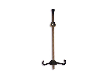
Another way to stack springs is to use the dual system. This system uses two springs on tip of each other in series. The difference is you also use a stop mechanism lock out nut that stops the travel of one of the springs at some point during shock travel to where the car is then riding on only one spring.
With this system you can run a softer rate on the top and a stronger rate on the bottom. When the shock travels, the divider between the shocks moves up the shock body. Once it reaches a predetermined point, the divider hits the stop and the top spring is no longer able to compress. Since only the bottom spring is now the only one working, its rate is what the car runs on, as long as the shock is compressed to the predetermined point.
Example:
200 x 200 = 40,000 (Top Spring Rate X Bottom Spring Rate)
200 + 200 = 400 (Top Spring Rate + Bottom Spring Rate)
40,000 ÷ 400 = 100 Rate
Drag Racing Front Spring Tech
Landrum designed their front drag racing coil springs to ”store” energy for instant, maximum weight transfer for launching. The springs are tall and constructed from small-diameter, high-tensile chrome silicon wire, providing the correct rate for the listed application.
Features
Note: To get the desired front end height (ride height), it may be necessary to modify the springs. A too-tall spring may be lowered by cutting off a portion of a coil (usually around 1/4 to 1/2 of the coil). Many factors affect the front end height, and wheel offset is a major consideration. A front wheel offset to the outside will increase leverage of the lower A-frame against the coil spring, and the nose of the car will be lower. Disc brake spacers will further impact the height. Adding or removing as little as 50 pounds can also make a difference. Take this into consideration when adding a fiberglass hood, aluminum heads, or when putting the battery in the trunk. Although these changes will alter the height of the car, the spring rates will be unaffected as long as you stay within the guidelines. The front end should always be weighed to ensure proper spring selection.
Landrum Performance front drag springs are designed for O.E.M. location spindles and Lower Control Arms. They will not work with drop spindles on drop lower control arms.
Below are suggestions on selecting a spring for your application.
Front End Weights
1200lbs – 1300lbs = 150 Rate
1300lbs – 1400lbs = 165 Rate
1400lbs – 1500lbs = 180 Rate
1500lbs – 1600lbs = 200 Rate
1600lbs – 1700lbs = 225 Rate
1700lbs – 1900lbs = 250 Rate